Step 3: Allocating Placement and Routing Region for a PR Partition
For every base revision you create, the PR design flow places the corresponding persona core in your PR partition region. To locate and assign the PR region in the device floorplan for your base revision:
- Right-click the u_blinking_led instance in the Project Navigator and click . The region appears on the Logic Lock Regions Window.
- Your placement region must enclose the blinking_led logic. Select the placement region by locating the node in Chip Planner. Right-click the u_blinking_led region name in the Logic Lock Regions Window and click .
The u_blinking_led region is color-coded.
Figure 4. Chip Planner Node Location for blinking_led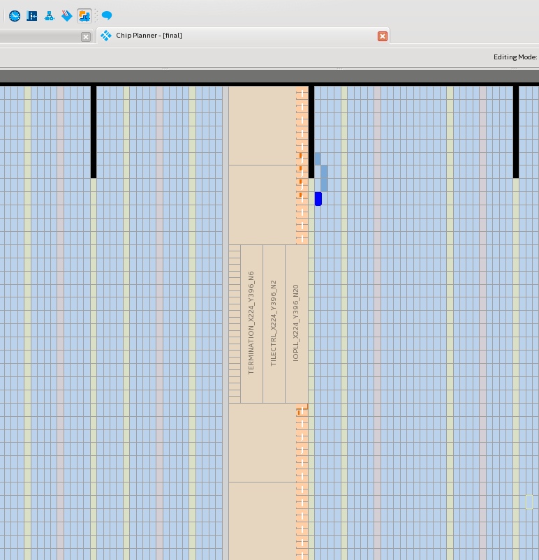
- In the Logic Lock Regions window, specify the placement region co-ordinates in the Origin column. The origin corresponds to the lower-left corner of the region. For example, to set a placement region with (X1 Y1) co-ordinates as (169 410), specify the Origin as X169_Y410. The Intel® Quartus® Prime software automatically calculates the (X2 Y2) co-ordinates (top-right) for the placement region, based on the height and width you specify.
Note: This tutorial uses the (X1 Y1) co-ordinates - (169 410), and a height and width of 20 for the placement region. Define any value for the placement region. Ensure that the region covers the blinking_led logic.
- Enable the Reserved and Core-Only options.
- Double-click the Routing Region option. The Logic Lock Routing Region Settings dialog box appears.
- Select Fixed with expansion for the Routing type. Selecting this option automatically assigns an expansion length of 1.
Note: The routing region must be larger than the placement region, to provide extra flexibility for the Fitter when the engine routes different personas.Figure 5. Logic Lock Regions Window
set_instance_assignment -name PLACE_REGION "X169 Y410 X188 Y429" -to \
        u_blinking_led
set_instance_assignment -name RESERVE_PLACE_REGION ON -to \
        u_blinking_led
set_instance_assignment -name CORE_ONLY_PLACE_REGION ON -to \
        u_blinking_led
set_instance_assignment -name ROUTE_REGION "X168 Y409 X189 Y430" -to \
        u_blinking_led