Visible to Intel only — GUID: kly1432259696132
Ixiasoft
1.1.3. Result
The simulation result of the reference design shows the behavior of:
- Reference clock (refclk) signal
- Reset (reset_n) signal
- Interface locked (locked) signal
- Correct data counter (correct_data_counter) values
- Transmitted and received data (group_0_data) bus
- Simulation complete (done) signal
Figure 6. Design Example Simulation Flow
The following shows the behavior of the signals.
Figure 7. Reset Signal De-assertion
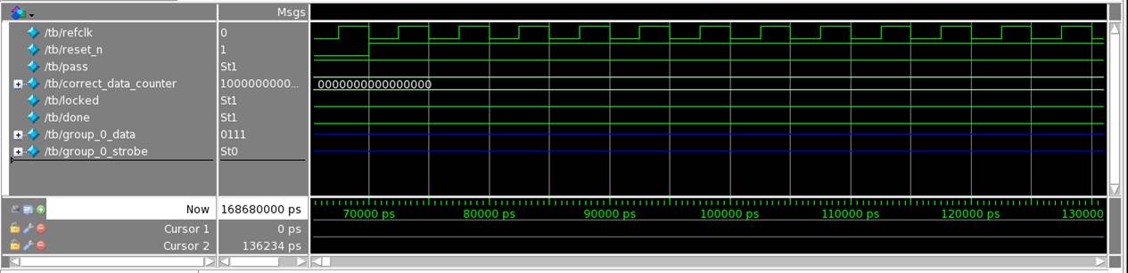
Figure 8. Data Transfer After Locked Signal Assertion
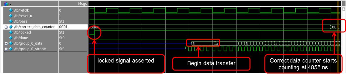
Figure 9. Simulation Complete with Done Signal Assertion
