Visible to Intel only — GUID: dmi1457446432770
Ixiasoft
1.2.1. BMS Reference Design Software Requirements
1.2.2. BMS Reference Design Hardware Requirements
1.2.3. Downloading and Installing the BMS Reference Design
1.2.4. Setting Up the MAX 10 Development Board
1.2.5. Compiling the FPGA Hardware Design for the BMS Reference Design
1.2.6. Compiling the Nios Software for the BMS Reference Design
1.2.7. Programming the BMS Reference Design Hardware onto the Device
1.2.8. Downloading the BMS Reference Design Nios II Software to the Device
1.2.9. MATLAB Simulink Top-Level Design for the BMS Reference Design
1.2.10. Running the BMS Reference Design in a System-in-the-Loop Simulation
Visible to Intel only — GUID: dmi1457446432770
Ixiasoft
1.2.9. MATLAB Simulink Top-Level Design for the BMS Reference Design
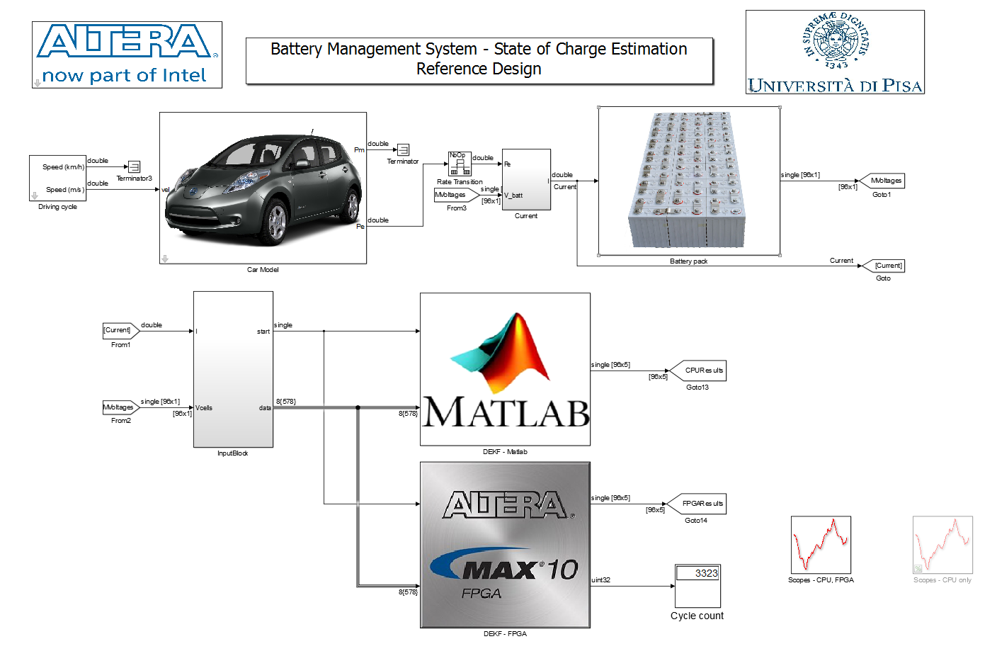
The reference design uses the Simulink model demo_top.slx, which calls setup_demo_top.m file to initialize all parameters.
Figure 4. Simulink Top-Level Design
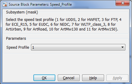
The driving cycle block allows you to select the speed profile.
Figure 5. Driving Cycle
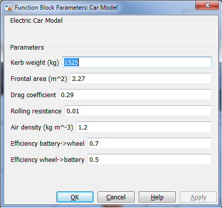
The car model block allows you to select the car model parameters.
Figure 6. Car Model
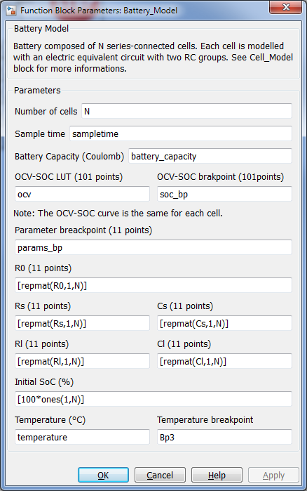
The battery pack contains the battery model block, which allows you to select the battery parameters.
Figure 7. Battery Model
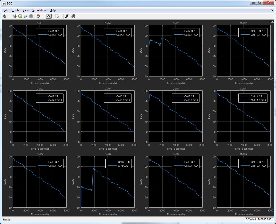
The DEKF-FPGA block communicates with the FPGA. It sends input, including initial values, voltage and current data, to the FPGA, and receives SOC estimation, and updated battery model parameters from the FPGA. Three scope windows, including cell 1 and 2 information, and SOC value for the first 12 cells, appear by default when you open the Simulink top level design. You can add more scopes in the floating scope block.
Figure 8. Cell Information
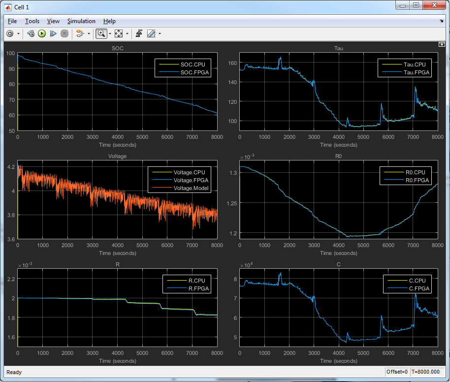
Figure 9. SOC values for 12 Cells