Visible to Intel only — GUID: wxf1476250983839
Ixiasoft
2.1.1. Constructing Communication Links in the Link Designer Module
2.1.2. Link and Simulation Setting
2.1.3. Transmitter Setting
2.1.4. Receiver Setting
2.1.5. IBIS-AMI Wrapper
2.1.6. Channel Setting
2.1.7. Batch Channel Simulation Configuration
2.1.8. Crosstalk Aggressor Transmitter Setting
2.1.9. Repeater and Retimer Configurations
2.1.10. Noise Source Link Component
2.1.11. System Options
2.1.12. Project Management Functions
2.1.13. Archiving and Unarchiving Projects
2.1.14. Device Model Importer
2.1.15. Analysis Functions and Pre-Simulation and Pre-Analysis Checklists
2.1.16. COM Analysis
2.1.17. Link Builder
Visible to Intel only — GUID: wxf1476250983839
Ixiasoft
2.1.9.2. Repeater/Retimer TX Configuration
- IBIS Files: Click the file open button (see Repeater/Retimer TX IBIS-AMI Configuration) next to the IBIS File text box to select an IBIS model file. Intel® Advanced Link Analyzer scans through the IBIS file and allocates all available transmitter components and models. If Intel® Advanced Link Analyzer encounters the following issues in opening or interpreting the IBIS-AMI model, a warning message is displayed.
- No transmitter component or model can be located.
- The DLL for the computer platform cannot be located. The IBIS-AMI model is platform dependent. For example, a 32-bit DLL is required to simulate in a 32-bit link simulator and a 64-bit DLL is required to simulate in a 64-bit simulator. A 32-bit DLL cannot simulate in a 64-bit DLL simulator.
- The DLL occupies too much memory and Intel® Advanced Link Analyzer was not able to load it. However, Intel® Advanced Link Analyzer might be able to run the simulation with such a DLL because of memory allocation differences in the Intel® Advanced Link Analyzer GUI and the simulation engine.
- Component: Select an IBIS component from the IBIS model
- IBIS tab
- Model: Select a device model within a component of an IBIS model.
- Model Selector: Select a model from the model selector list.
- Corner: Select the corner type of a device model. The choices are Typ, Min, and Max.
- AMI File: Shows the AMI file specified in the IBIS model.
Note: Intel® Advanced Link Analyzer currently only supports device models with AMI modeling components.
- DLL File: Shows the DLL file specified in the IBIS model.
- Use External Termination: Indicates that an external termination is used in the simulation. The external termination (single-ended) is specified in the text box on the right. The default setting is not using external termination and the default external termination (if applicable) is 50 ohms (single-ended).
- Use Rising/Falling Waveform: If rising/falling waveforms are available in the IBIS model, the rising/falling waveforms are used to model the transmitter by default. If you turn off this option, ramp data (in the IBIS model) is used in the simulation.
- Automatic Jitter/Noise Update: Allows automatic jitter/noise updates from the IBIS-AMI model (available for models which are compliant with IBIS-AMI 6.0 and later).
Note: If you noticed very slow GUI response with certain IBIS-AMI models, turn off Automatic Jitter/Noise Update to see if the condition improves. You can import jitter/noise number using Manual Jitter/Noise Update.
- Manual Jitter/Noise Update: When the Automatic Jitter/Noise Update option is disabled, turning on this option allows you to manually update the jitter/noise figures from the IBIS-AMI model (available for models which are compliant with IBIS-AMI 6.0 and later).
- DLL_Path: Specify a folder or path name where the supporting files of an IBIS-AMI model are stored. Refer to the IBIS standards for details.
- Model Option: Choose Default.
- Ideal Front-end Limiting Amplifier: If on, Intel® Advanced Link Analyzer inserts an ideal limiting amplifier before the repeater/retimer driver stage with a waveform differential amplitude of 1 V.
- AMI tab: Refer to IBIS-AMI Transmitter in the Characterization Data Access section for details.
- Jitter/Noise: Refer to IBIS-AMI Transmitter in the Characterization Data Access section for details.
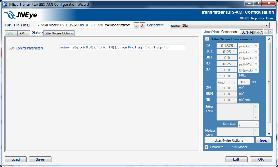
- Status tab: Refer to IBIS-AMI Transmitter in the Characterization Data Access section for details.
- Jitter/Noise Options: Internal use only. Do not use and let it remain in its default state.
Figure 87. Repeater/Retimer TX IBIS-AMI Configuration
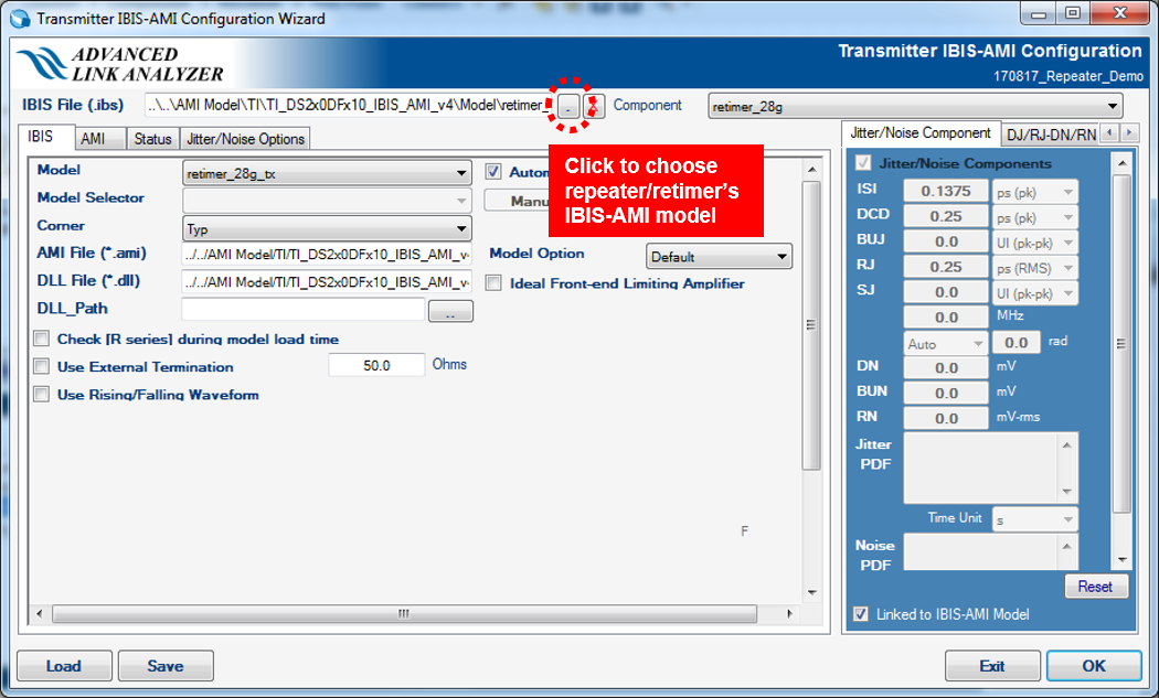
Figure 88. Repeater/Retimer TX AMI Tab
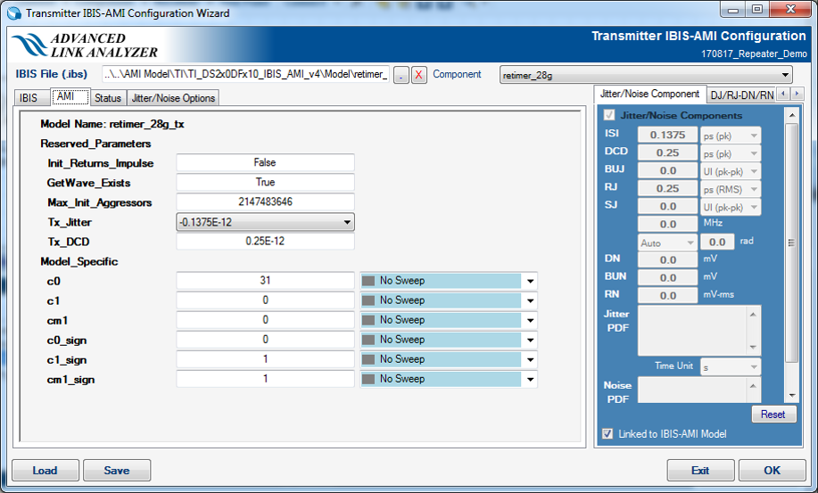
Figure 89. Repeater/Retimer TX Status Tab
Related Information