Visible to Intel only — GUID: jba1434040209938
Ixiasoft
1.6.1. Initial Stackup Entry
1.6.2. Using the Correct Number of Power/Ground Via Pairs
1.6.3. Using the Correct Number of Power/Ground Via Pairs and Layer Number
1.6.4. Corrected Number of Power/Ground Via Pairs and Layer Numbers
1.6.5. Moving Supplies to Optimal Layers
1.6.6. Moving Power and Ground Planes Closer Together
1.6.7. Move Decoupling Capacitors to the Top Surface of the PCB
1.6.8. Using X2Y Decoupling Capacitors
1.6.9. Using Ultra–Low ESR Bulk Capacitors
1.6.10. Swapping VCC on Layer 9 with VCC, VCCT_GXB, and VCCR_GXB on Layer 4
1.6.11. Assessing How Much Total Capacitance Might be Required
1.6.12. Using the Core Clock Frequency and Current Ramp Up Period Parameters
1.6.13. Overall Design Study Capacitor Savings
1.6.14. Overall Summary
1.6.15. References
Visible to Intel only — GUID: jba1434040209938
Ixiasoft
1.6.1. Initial Stackup Entry
The initial layer-stack of this design study is shown below.
Figure 5. Initial Stackup
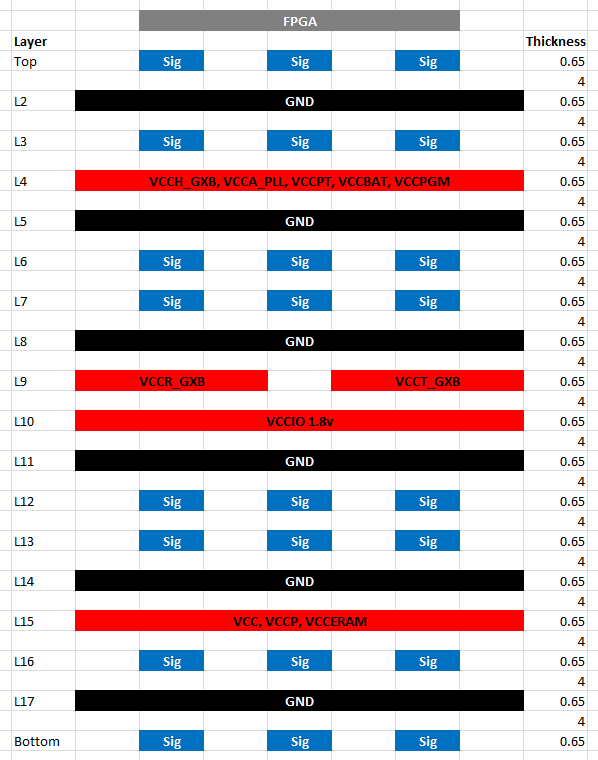
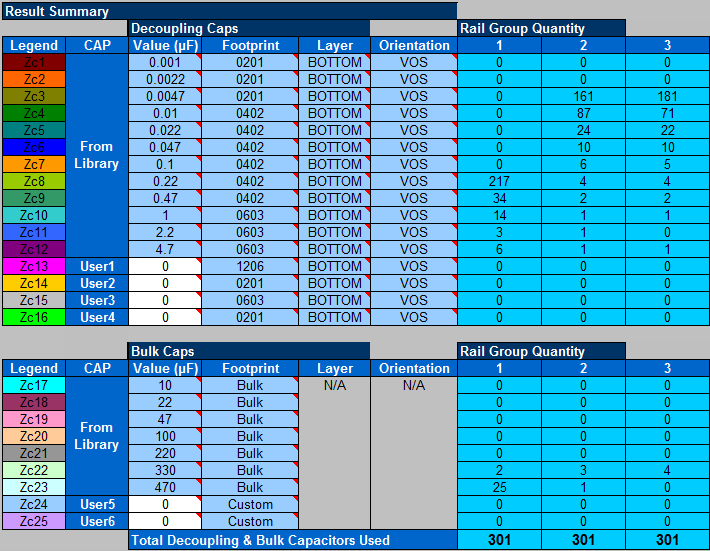
When entered into the PDN Tool, and Auto decoupling mode is selected for all power groups, it reports 301 capacitors are required to decouple each of the VCC, VCCT_GXB and VCCR_GXB supplies. When the PDN Tool decoupling mode is set to Auto, it will not add more than 301 capacitors. In reality, more than 301 capacitors will be required to decouple the design. Fitting in excess of 903 capacitors for three supplies is unrealistic so optimization of the PCB PDN is required.
Auto decoupling mode is used throughout this application note.
Figure 6. Initial Number of Required Decoupling Capacitors
The following figure shows the impedance plots for VCC, VCCT_GXB and VCCR_GXB with this initial stackup and PDN Tool configuration.
Figure 7. Initial VCC, VCCT_GXB, and VCCR_GXB Supply Impedance Plots
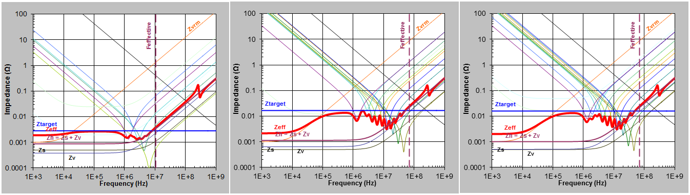
With this initial stackup and PDN Tool configuration, Feffective for the VCC supply is reported to be just 10.62MHz and the target Feffective of 70MHz for VCCT_GXB and VCCR_GXB supplies are not met. This is because the initial stackup, layer allocation, and PDN is not optimized, resulting in an inefficient PDN.
Figure 8. Initial VCC Supply Feffective
