Visible to Intel only — GUID: csq1692201125147
Ixiasoft
2.1. Compilation Overview
2.2. Using the Compilation Dashboard
2.3. Design Netlist Infrastructure
2.4. Using the Node Finder
2.5. Analysis & Elaboration Flow
2.6. Design Synthesis
2.7. Design Place and Route
2.8. Incremental Optimization Flow
2.9. Fast Forward Compilation Flow
2.10. Full Compilation Flow
2.11. Compilation Monitoring Mode
2.12. Exporting Compilation Results
2.13. Integrating Other EDA Tools
2.14. Compiler Optimization Techniques
2.15. Synthesis Language Support
2.16. Synthesis Settings Reference
2.17. Fitter Settings Reference
2.18. Design Compilation Revision History
2.6.3.1. Registering the SDC-on-RTL SDC File
2.6.3.2. Applying the SDC-on-RTL Constraints
2.6.3.3. Inspecting SDC-on-RTL Constraints
2.6.3.4. Creating Constraints in SDC-on-RTL SDC Files
2.6.3.5. Using Entity-Based SDC-on-RTL Constraints
2.6.3.6. Types of SDC Files Used in the Intel® Quartus® Prime Software
2.6.3.7. Example: Using SDC-on-RTL Features
Targeting Pins of Top-level Instances
Targeting Pins in Cells
Targeting Pins Using Wildcards
Example 4. Applying Constraints at Deeper Hierarchies
Entity-Based SDC-on-RTL
2.12.1. Exporting a Version-Compatible Compilation Database
2.12.2. Importing a Version-Compatible Compilation Database
2.12.3. Creating a Design Partition
2.12.4. Exporting a Design Partition
2.12.5. Reusing a Design Partition
2.12.6. Viewing Quartus Database File Information
2.12.7. Clearing Compilation Results
3.1. Factors Affecting Compilation Results
3.2. Strategies to Reduce the Overall Compilation Time
3.3. Reducing Synthesis Time and Synthesis Netlist Optimization Time
3.4. Reducing Placement Time
3.5. Reducing Routing Time
3.6. Reducing Static Timing Analysis Time
3.7. Setting Process Priority
3.8. Reducing Compilation Time Revision History
Visible to Intel only — GUID: csq1692201125147
Ixiasoft
2.6.3.7. Example: Using SDC-on-RTL Features
This topic provides some examples of how to use SDC-on-RTL features and set up timing constraints in your design.
You can work with both new and pre-existing designs that incorporate components from diverse sources, including Verilog, VHDL, IPs, and Platform Designer. Suppose your designs contain nodes that require constraint definitions, such as clocks, generated clocks, or asynchronous paths, across various hierarchy levels. In that case, you can efficiently target them using SDC-on-RTL constraints. It is imperative that your chosen design successfully passes the Analysis & Elaboration stages within the compilation flow for seamless and effective testing process.
Note: Currently, Intel® Quartus® Prime IPs use conventional SDCs only, which means if you want to create SDC-on-RTL constraints that interact with IP clocks, define them initially with SDC-on-RTL constraints. These clocks can eventually be overwritten by the IP SDCs. Alternatively, if you do not need the clocks defined at Elaboration, use derive_clocks during Post-Synthesis Static Timing Analysis (STA) to automatically generate clocks temporarily for the Timing Analyzer session.
The following steps demonstrate the process of setting up timing constraints for your designs by targeting RTL node names:
- Click New in the left-hand Tasks pane. The New dialog appears.
- Click SDC File targeting RTL Names (Read and stored after elaboration).
Figure 55. New Dialog Box
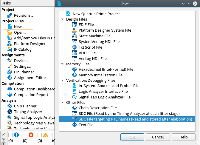
- Click OK.
- Within the new SDC-on-RTL file, formulate a comprehensive set of constraints targeting nodes by their RTL names. For information about how to obtain a list of the supported commands, refer to Creating Constraints in SDC-on-RTL SDC Files.
- Ensure the constraint targets are correct and the selected design passes the Analysis & Elaboration compilation stage as the constraints are read during this stage and applied to the elaborated netlist. This step is pivotal as it empowers the software to generate a database of your design. Additionally, it grants access to various checkpoints from where you can access the RTL Analyzer.
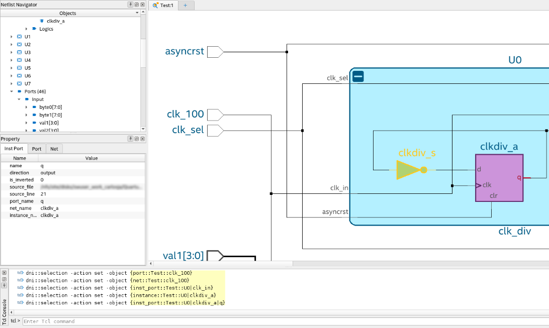
Note: The RTL Analyzer assists you in locating specific netlist nodes within your design that require constraint application. It allows you to navigate your design and select your desired target nodes. Subsequently, you can use corresponding Tcl commands generated within the Tcl console to extract hierarchical node names from the Tcl commands. This process streamlines the task of implementing constraints on the netlist nodes. For more information about the RTL Analyzer, refer to Exploring the RTL Analyzer.Figure 56. Locating Specific Netlist Nodes in the RTL Analyzer
Alternatively, you can locate nodes within your target netlist using the Find tool, which is available from the Edit menu in the RTL Analyzer. The Find tool allows you to search objects within the updated database from the checkpoint accessed.
Figure 57. Find Dialog in the RTL Analyzer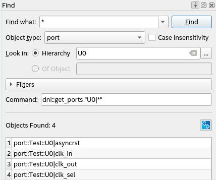
In addition, you can create your collections by focusing on the inputs and outputs of your design through the use of the get_ports command. Within your design, you can locate specific nets using the get_nets command or target pins using the get_pins command.
After establishing your timing constraints in your designs, use the following examples as a guide to set up your constraints, specifically focusing on RTL node names, thereby ensuring precision and efficiency throughout your design process.
Targeting Pins of Top-level Instances
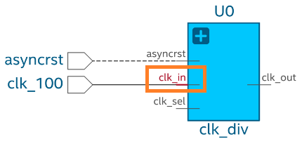
In certain scenarios, it is necessary to constrain pins of top-level instances. For example, when defining clocks and reset inputs, you can utilize the get_pins Tcl command followed by the hierarchical pin name to filter each pin as shown in the following:
get_pins U0|clk_in
This Tcl command returns the input pin clk_in in the instance U0.
Figure 58. Targeting Pins of Top-level Instances
Similarly, you can target other pins of the same instance and apply necessary constraints as shown in the following:
create_clock -name clk_input -period 10 [get_pins U0|clk_in]
create_generated_clock -name clk_output -source [get_pins U0|clk_in] -divide_by 2 [get_pins U0|clk_out]
Targeting Pins in Cells
When constraining your design, you might need to target cell pins to apply constraints. In such scenarios, you can use the get_pins Tcl command and RTL names to locate specific cell pins, such as clk or d inputs and q outputs. For example:
get_pins U6|reg_a[0]|clk
get_pins U6|reg_a[0]|d
get_pins U6|reg_a[0]|q
Figure 59. Targeting Pins in Cells Example
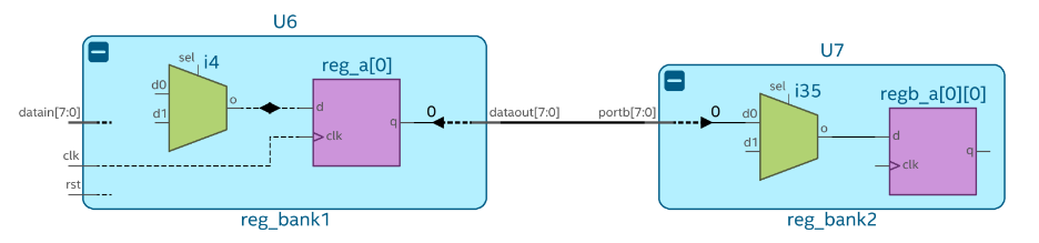
These Tcl commands return specific pins of the reg_a[0] register in the U6 instance. You can use the returned collection to constrain paths. For example, from U6|reg_a[0] to U7|regb_a[0][7] as follows:
set_false_path -from [get_pins U6|reg_a[0]|clk] -to [get_pins U7|regb_a[0][0]|d]
Targeting Pins Using Wildcards
Within your design, you might need to constrain several pins with similar properties and names. In this case, use wildcards to filter the results.
Note: Use the wildcards judiciously and ensure the scope does not include more targets than necessary. Targeting extraneous nodes can limit optimizations and increase compilation runtime and memory.
The get_pins command can target buses porta or portb of U7, as shown in the following:
get_pins U7|porta[*]
get_pins U7|portb[*]
Figure 60. Targeting Pins Using Wildcards Example
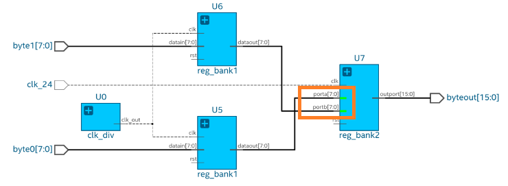
The Tcl command returns a collection of pins from porta[0] to porta[7] and from portb[0] to portb[7]. You can use the returned collection to constrain all objects simultaneously, as shown in the following:
set_false_path -from [get_pins U5|rega*|clk] -to [get_pins U7|porta[*]]
set_false_path -from [get_pins U6|rega*|clk] -to [get_pins U7|portb[*]]
Example 4. Applying Constraints at Deeper Hierarchies
Within your design, you can apply constraints at different levels of hierarchy using the pipe character (|) to separate hierarchy levels of instances. Constraints are applied when the hierarchy levels match and the string values, including wildcards, match the pin names. For example:
get_pins U3|U0_lv1|U0_lv2|U0_lv3|flag
The fundamental timing analysis flow requires executing the fitter to elaborate the timing netlist before applying any constraints. In the following example, suppose you intend to constraint a generated clock buried deep within module A:
Figure 61. Applying Constraints at Deeper Hierarchies Example
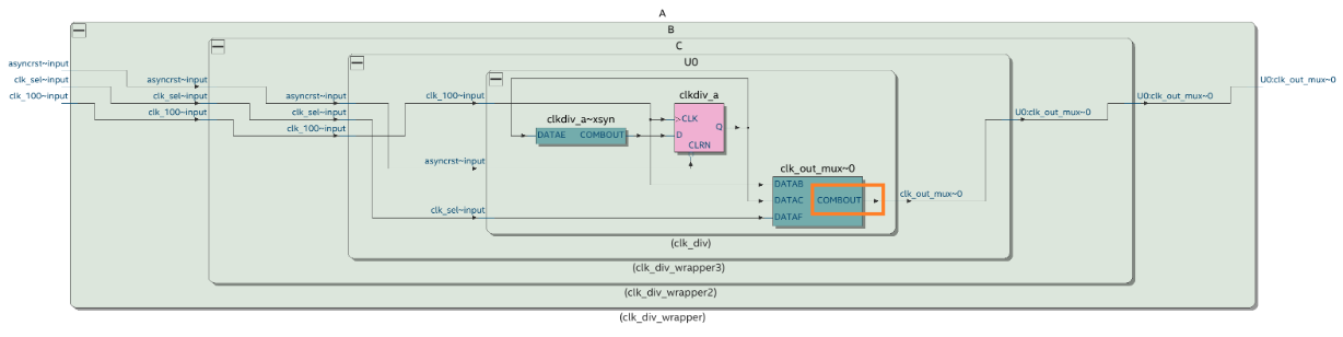
To achieve this, locate the cell clk_out_mux where the constraint must be applied and identify the pin name COMBOUT. This process often results in a complex path name that can be challenging to decipher, especially when module names are intricate (unlike straightforward names, such as A|B|C). Additionally, suppose the hierarchy evolves in the future. In that case, you must rerun the fitter and delve into the design again to derive the updated path, which can lead to inconsistencies between the design and the constraint targets. You can target the COMBOUT pin as follows:
get_pins A|B|C|U0|clk_out_mux~0|combout
SDC-on-RTL also offers an efficient means of constraint propagation, enabling you to apply constraints at module boundaries. It ensures that these constraints seamlessly extend to the corresponding leaf instances during the synthesis stage. For instance, revisit the previous example, in which the clock constraint embedded within module A can be established using SDC-on-RTL constraints at the module A's boundaries, specifically focusing on the clk_out pin.
Figure 62. Deeper Design Hierarchies
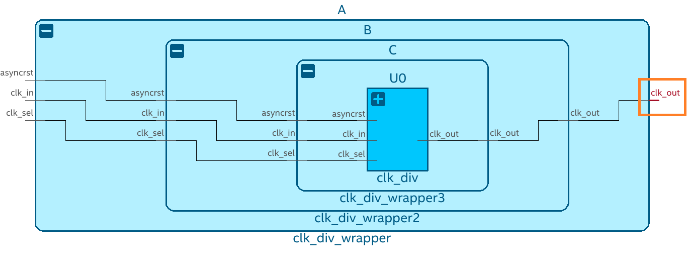
To target the clk_out pin of module A, use the following filter:
get_pins A|clk_out
By directing your attention towards pins located at the boundaries of abstract blocks, you gain the flexibility to modify the internal instance hierarchy as needed. Constraints remain effective even if you decide to rename an internal instance within your module, for instance, changing it from A|B|C|U0 to A|X|Y|U0. Importantly, this can be accomplished without requiring alterations to your existing constraints. This demonstrates the robust capabilities of SDC-on-RTL, allowing you to concentrate on boundary pins rather than navigating complex hierarchies. This approach ensures constraint accuracy and simplifies constraint management.
After creating the constraints, rerun the Analysis & Elaboration on the compilation dashboard so that constraints are read and applied to your design. Open the constrained checkpoint of the RTL Analyzer and carefully select the nodes where the constraints were applied. Utilize the Property Viewer to verify the correct application of constraints to these nodes.
Figure 63. Property Viewer in the RTL Analyzer

Utilize the Intel® Quartus® Prime software's additional tools to explore and confirm that all SDC constraints were read and successfully applied. Tools like the Constraints viewer launched from the RTL Analyzer can assist you in verifying and cross-probing the constraints with the Schematic Viewer.
Figure 64. Constraints Viewer

Additionally, the reports under Compilation Report > SDC Constraints folder provide a detailed view of the constraints and their locations. Use the Constraint Propagation Report to view how constraints are propagated as the netlist is transformed and inspect where the constraints end up post optimizations.
Important: These tools offer valuable means to verify the accurate application of your constraints. However, if you intend to iterate on the process of defining constraints using the SDC-on-RTL approach, you must rerun the Analysis & Elaboration stage each time. This iterative approach ensures that the constraints are meticulously analyzed during netlist generation, resulting in enhanced performance and seamless integration with your design.
Entity-Based SDC-on-RTL
In typical designs, a combination of third-party IPs and actively evolving RTL components co-exist. With the SDC-on-RTL constraints feature, you can define precise constraints at module boundaries. This methodology liberates you from the need for intricate knowledge about the internal implementation of these blocks when instantiating modules or IPs.
The entity-based SDC-on-RTL approach enhances this functionality by prefixing filters with the full path name of each IP, creating a protective barrier around their SDC constraints. This encapsulation effectively safeguards against unintended SDC leaks and other design paths that might coincidentally share a name. This safety is necessary because timing constraints specified in an SDC-on-RTL file are generally applied globally across an entire project rather than confining themselves to specific entities. Consequently, even if you lack precise knowledge about an instantiated IP or employ multiple instances of the same IP, your constraints remain effective, and you can prevent unexpected SDC leaks.
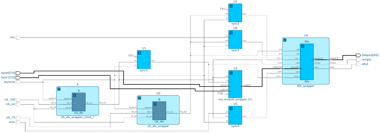
Entity-based SDC-on-RTL constraints provide enhanced flexibility in your design process. You can override constraints that target RTL names by introducing additional SDC constraints during the implementation stage. To understand this concept, consider the following example that establishes logical constraints for post-synthesis timing analysis using an entity-based SDC-on-RTL approach. This example focuses on two instances of clk_div and an additional fifo instance, as shown in the following:
Figure 65. Entity-Based SDC-on-RTL Design Example
Follow these steps to apply entity-based SDC-on-RTL constraints:
- Apply global SDC-on-RTL constraints to the design.c
# sdc_on_rtl_global.rtlsdc

create_clock -period 100MHz [get_ports clk_100]
create_clock -period 75MHz [get_ports clk_75]
- Use the File Properties dialog to assign this rtlsdc file as the SDC File Targeting RTL names or use the following QSF assignment:
set_global_assignment -name RTL_SDC_FILE <filename>
Figure 66. File Properties Dialog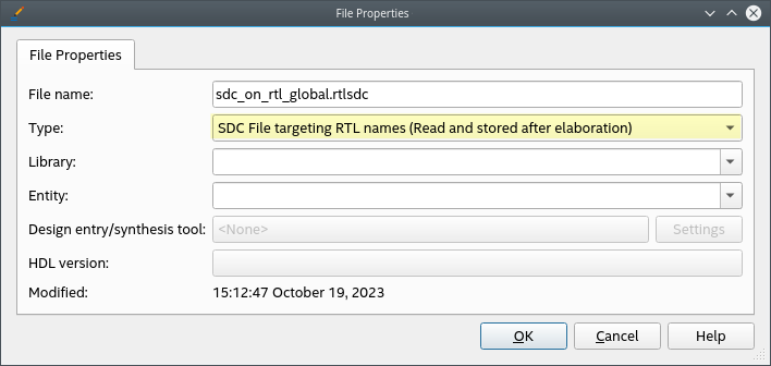
- Define the files that will be assigned to specific modules in your design using the RTL_SDC_FILE argument followed by the -entity and -library arguments, as shown in the following:
set_instance_assignment -name RTL_SDC_FILE clk_dic.rtlsdc -entity clk_div_wrapper -library clk_div_wrapper
set_instance_assignment -name RTL_SDC_FILE fifo.rtlsdc -entity fifo -library fifo
The QSF definition effectively reduces the scope of each RTLSDC file to the entities that match the assigned name. Subsequently, it is imperative to establish the constraints that rule over each module.
Some internal connections within modules or IPs may remain partially unknown during the initial stages, mainly when the RTL netlist is generated. Therefore, apply the constraints at the module boundaries, specifically at each module's input and output boundaries.
When targeting the inputs and outputs of a module, there are two distinct types of selections at your disposal:
- inst_port: These elements are retrieved in collections due to applying the get_pins filter. They target inputs and outputs of modules in a manner similar to addressing pins on registers and LUTs.
get_pins {clk_in} inside clk_dic.rtlsdcNote: Using get_pins is recommended for constraints that expect pins as targets.Figure 67. Instance Port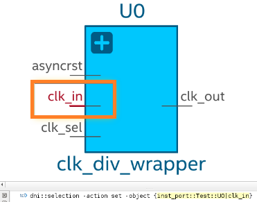
- port: These elements reside within the module and are primarily used to target ports in entity-bound constraints. You can employ the get_ports filter for this purpose.
get_ports {clk_in} inside clk_dic.rtlsdcNote: Using get_ports is recommended for constraints that expect ports as targets.Figure 68. Ports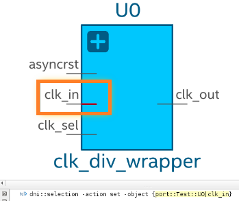
These constraints facilitate the creation and propagation of output clocks generated from the incoming reference clock. The actual connections in the RTL netlist between the clock source and the target are optional at the initial stage. The constraints are identified and accounted for by the post-synthesis Timing Analyzer. For instance, in the case of the clk_div modules where the inner content remains unknown but the output behavior is known, define a multiplexed clock as shown in the following:
# clk_dic.rtlsdc

set current_instance [get_entity_current_instance];
create_generated_clock -name ${current_instance}_clk_mux_2 -source [get_ports clk_in] -divide_by 2 [get_ports clk_out]
create_generated_clock -name ${current_instance}_clk_mux_1 -source [get_ports clk_in] [get_ports clk_out] -add
In contrast, for the fifo module where access to the inner logic is available, you can still define the constraints using the entity-bound approach, especially when multiple instances of the same module share identical constraints.
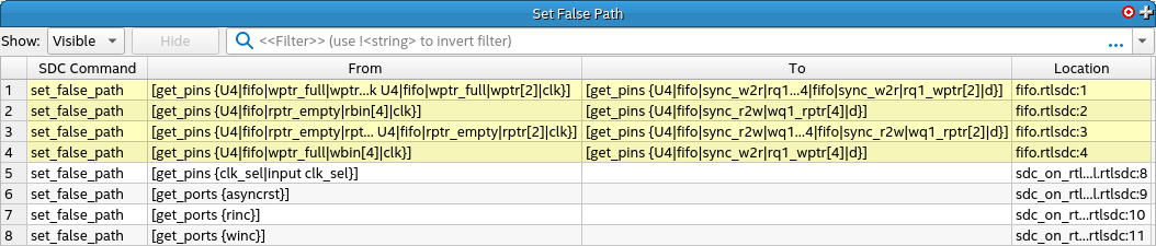
# fifo.rtlsdc

set_false_path -from [get_pins wptr_full|wptr[*]|clk] -to [get_pins sync_w2r|rq1_wptr[*]|d]
set_false_path -from [get_pins rptr_empty|rbin[4]|clk] -to [get_pins sync_r2w|wq1_rptr[4]|d]
set_false_path -from [get_pins rptr_empty|rptr[*]|clk] -to [get_pins sync_r2w|wq1_rptr[*]|d]
set_false_path -from [get_pins wptr_full|wbin[4]|clk] -to [get_pins sync_w2r|rq1_wptr[4]|d]
Once the constraints are meticulously defined, during the Analysis & Elaboration stage, messages confirm that each file is appropriately read according to its assigned module, as shown in the following image:
Figure 69. Message Dialog

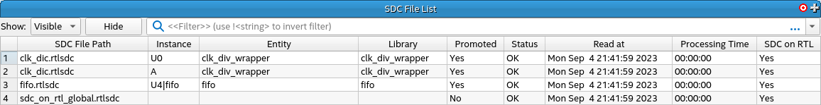
You can further validate this information in the SDC File List report within the post-synthesis Timing Analyzer. This report furnishes a comprehensive list, delineating each SDC file read, its assigned instance, and its alignment with the SDC-on-RTL approach.
Figure 70. SDC File List Report in the Timing Analyzer
You must confirm the application of constraints according to their targets and purpose. For instance, you can examine the generated clocks and false paths to confirm that the constraints have been effectively implemented, as shown in the following:
Figure 71. Create Generated Clock Window in the Timing Analyzer
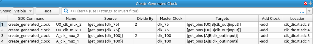
Figure 72. Set False Path Window in the Timing Analyzer
By following this example, you can seamlessly assign SDC-on-RTL constraints to specific modules within your design. This approach ensures the accurate integration of third-party IPs, even in cases where modules are partially unknown or extensively replicated.