4.14. Intel® Stratix® 10 EPE - Report Worksheet
The Report worksheet shows all the information and power estimation results from the Early Power Estimator for Intel® Stratix® 10 devices.
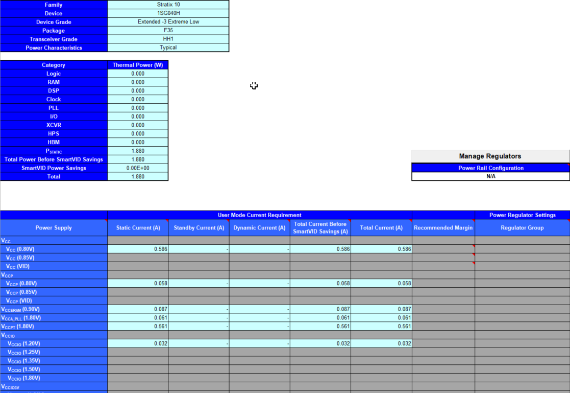
Figure 22. Report Worksheet of the Early Power Estimator
| Input Parameter | Description |
|---|---|
| Power Rail Configuration | Selects a power rail configuration for assignment of supply rails to regulator groups. This field is enabled regardless of the Power Characteristics setting in the Main worksheet. You receive a warning message if you select a power rail configuration when the Power Characteristics setting is Typical. Choose Custom to manually enter regulator group selection, or to modify the results of automatic selection. |
The Report worksheet provides current requirements for each voltage rail, expressed in terms of static current, standby current, dynamic current, and total current.
| Module | Parameter | Description |
|---|---|---|
| User Mode Current Requirement | Power Supply | Indicates the power supply rail name and voltage applied to the specified rail (in V). |
| Static Current (A) | Indicates the component of current consumed from the specified power rail whenever the power is applied to the rail, independent of circuit activity (in A). This current is dependent on device size, device grade, power characteristics and junction temperature. | |
| Standby Current (A) | Indicates the component of active current drawn from the specified power rail by all modules on all worksheets, independent of signal activity (in A). This current is independent of device grade, power characteristics and junction temperature. Standby current includes, but is not limited to, I/O and transceiver DC bias current. Device size has only a small impact on transceiver DC bias current. | |
| Dynamic Current (A) | Indicates the component of active current drawn from the specified power rail due to signal activity of all modules on all worksheets (in A). This current depends on device size, but is independent of device grade, power characteristics and junction temperature. | |
| Total Current Before SmartVID Savings (A) | Indicates the total current consumed from the specified power rail before SmartVID savings (in A). The sum of static, standby, and dynamic currents. | |
| Total Current (A) | Indicates the total current consumed from the specified power rail (in A). For devices and rails supporting SmartVID, this column shows total current after SmartVID power savings; otherwise, the current reported in this column should equal the sum of static, standby, and dynamic currents. | |
| Recommended Margin | Indicates the recommended margin on total current for regulator sizing. The recommended margin on the Vcc rail is calculated based on the ratio of dynamic to static power.
Note: Recommended Margin is reported only for devices with final power models, and only when the Power Characteristics field on the Main worksheet is set to Maximum.
|
|
| Power Regulator Settings | Regulator Group | Indicates the regulator group number to which this supply is assigned. Regulator group numbers correspond to the group numbers shown in the Enpirion worksheet. If you select an automatic assignment mode in the Power Rail Configuration field, the regulator group numbers also correspond to the group numbers in the pin connection guidelines. To edit fields in this column manually, select Custom under Power Rail Configuration. |